Computed tomography in oral and maxillofacial radiology
Computed tomography (CT) is today commonly used in imaging of the maxillofacial area. Conventional CT examinations are usually performed in medical X-ray departments. However, a relatively new technique named cone-beam computed tomography (CBCT) or digital volume tomography (DVT) has now also become available for dental purposes. The advantage with this technique is a lower radiation dose compared to conventional CT. Common examples when DVT is used are; for diagnosing the position of impacted canines and suspected root resorption of the adjacent lateral incisor, preoperative planning of implant treatment and examination of periapical areas when intraoral radiography has given uncertain information. Conventional CT is used for examination of larger areas in diagnosing e.g. facial anomalies, extensive traumata and tumours.
Computed tomography (CT) is today frequently used in imaging of the oral and maxillofacial region. All radiological examinations must be based on clinical information and relevant clinical questions that should be answered. A useful investigation is one, in which the result – positive or negative – will alter patient management or add confidence to the clinician’s diagnosis (1). This is especially important regarding CT because the examination is expensive and might give very high radiation doses to the patient. CT has the advantage over other radiographic techniques in that it has an inherent high-contrast resolution and tissues that differ in physical density by less than 1 % can be distinguished.
CT is a digital technique providing images of thin slices with variable thickness. The technique was described in 1972 by Allan McLeod Cormack and Godfrey Newbold Hounsfield, an invention for which they received the Nobel Prize in 1979. Hounsfield constructed a machine where the X-ray tube rotated around the patient and a thin slice (8 mm) of the patient was scanned. In the first generation of CT machines the image reconstruction time was around 30 minutes per slice. Today CT machines are available that scan more than 100 mm/s with the images appearing on the monitor almost instantaneously. By simultaneously scanning several slices of the body (multislice CT), the scan time can be reduced significantly and the smallest details (resolution around 0.3 mm) can be imaged within short scan times. Multislice CT machines are common in medical radiology departments; the slice thickness is usually less than 1 mm by use of very small X-ray detectors and a fan-shaped X-ray beam transmitted through the patient.
Apart from the types of CT machines described, DVT has now become available for maxillofacial imaging. In contrast to conventional CT, where slices are scanned DVT produces an image volume from a large number of conventional x-ray images. From this volume, slices of different thicknesses can be reconstructed in any plane. One advantage with DVT over conventional CT is the lower radiation dose. The scan time is relatively short (around 20 seconds) and the geometric resolution is high for some machines (3 line pairs/mm in Accuitomo F17®, J.Morita Co, Kyoto, Japan). Most machines have the appearance of a panoramic machine and the software is usually adapted to maxillofacial imaging.
In both DVT and conventional CT artefacts are produced, which can create problems in the reconstruction and interpretation of the images. The most common artefact in the maxillo-facial region is produced by metal objects and it is important to try to avoid exposing metal fillings and crowns. Fig. 1 A shows an example of metal artefacts from a post in conventional CT and Fig. 1 B from root-filling material in DVT.
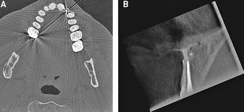
Fig. 1. A: Metal streaking artefacts in conventional CT from a post. B: A dark band is seen along the root-filling. The band is produced by an artefact and it is not depending on an inadequate root-filling.
Radiation dose
The Swedish Radiation Protection Authority in 2002 reported that CT is used in about 7 % of all radiological examinations in Sweden, but gives one third of the total dose to the population. Its use is rapidly increasing (2).The radiation dose for DVT can be considerably lower than that from conventional CT (3). The effective dose from DVT examinations varies substantially, depending on the device, imaging field and selected technique factors (4). When conventional CT is used low-dose protocols are now recommended whenever possible. A low-dose CT examination of the paranasal sinuses, for example, gives a dose similar to that from a conventional, digital radiographic examination but with substantially better diagnostic quality (5).
Cone beam computed tomography or digital volume tomography
Since this method was first introduced for imaging of the jaws in the late 1990s, several machines have been constructed by many manufacturers around the world. This can be seen as reflecting a need of more accurate imaging of the often anatomically complex structures of the jaws where, in conventional imaging, structures outside the region of interest often become superimposed on the latter making diagnosis difficult. It also may be seen as a need of a less expensive and, not least, less dose requiring technique than conventional CT.
With the very rapid development of DVT machines it is hard to know exactly how many of these are currently on the market. Suffice it to say that the variation among them in many important aspects is greater than that between conventional CT machines. They vary, e.g. in regard to: the size of the volume that can be examined; the size of the elements that make up the volume (the volume elements – or voxels); the thickness of the slices that can be obtained; how the positioning of the volume is achieved; spatial and contrast resolution; image quality; radiation doses; image capturing technique and whether the patient is examined in a sitting, standing or supine position. Some of these differences probably depend on whether manufacturers considered their machines a substitute for conventional CT for certain diagnostic tasks, a complement to it, or a combination of both. For some diagnostic tasks in the head and neck region, requiring good resolution of soft tissues, as in the diagnosis of malignant tumours and when examining the severely traumatized patient, conventional CT is still the method of choice. In a radiology department, DVT can thus be considered a complement to conventional CT. However, many tasks that previously could only be managed by CT can now be handled by means of DVT, often with better results. Other tasks, for which one rarely contemplated the use of CT, due to both higher radiation doses and costs as well as less satisfactory results, can now be handled by DVT.
The potential buyer of a DVT equipment thus has to contemplate what diagnostic problems one wants to solve with the aid of such a device and what is required of it in order to achieve sufficiently good results.
A common denominator for all DVTmachines is that a cylindrical volume is examined. For most equipments the size of the volume to be examined can be selected from a number of possible ones. From the examined volume slices are made in three perpendicular planes and, within given limits, the thickness of the slices can be selected. Generally seen, the radiation dose goes up with the size of the examined volume, when the same exposure parameters are used. However, there are major differences between the machines used.
In our experience most diagnostic problems in the jaws can be solved by the use of rather small volumes. Larger volumes than 8 cm x 8 cm are rarely needed, and when they are, the examinations can be made with a medical CT unit. When the information required concerns hard tissues only, the use of a low-dose-protocol can yield doses on a par with those from a DVT examination. When detailed soft tissue information is required medical CT examinations must be used.
DVT examinations are mainly used for: pre-implant planning purposes (Figs. 2 and 3) and for post-operative examinations when problems have arisen (Fig. 4); assessment of pain in the jaws, and presurgical assessment of endodontically treated teeth with remaining problems (Fig. 5); determination of anatomy and position of non-erupted teeth and their influence on neighbouring tooth structures (Figs. 6 – 8). Other applications are assessments of dento-alveolar traumata, temporomandibular joint problems, cystic lesions, and tumours, in short, all types of problems for which three-dimensional information is of essence.
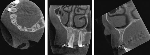
Fig. 2. Preoperative radiographs of a patient with missing upper lateral incisors. In the cross-sectional view (lower right image) of the left lateral incisor region very accurate measurements of height and width of the alveolar bone can be made. In the frontal view the inclination of the roots of neighbouring teeth can be assessed and their conditions apical and marginal conditions evaluated.
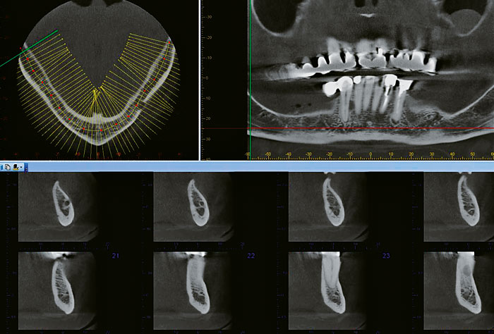
Fig. 3. In an axial view a curve can be drawn corresponding to the jaw curvature. Cross-sectional views are then obtained perpendicular to the tangent to the curve. Here only cross-sectional radiographs, from the mental foramen to just mesial of 43, are shown.
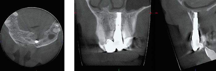
Fig. 4. Patient with pain after having received an implant. The radiographs show a large lesion in the palatal part of the alveolar bone with a thinning of the lower anterior border of the nasal cavity.
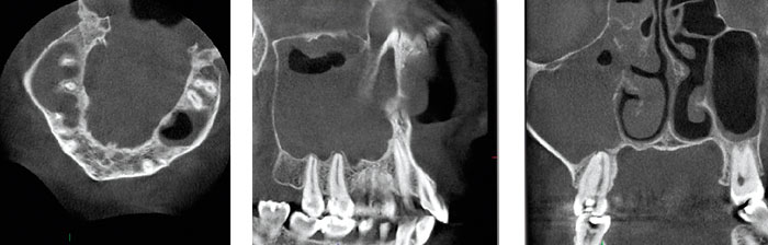
Fig. 5. In a patient with several episodes of unilateral maxillary sinuitis, a DVT examination showed an almost completely filled right maxillary antrum and soft tissue swellings in neighbouring ethmoidal cells. At the apical part of the upper right second molar, a small lesion is seen at the apex of its palatal root, which is fused with the disto-buccal root.
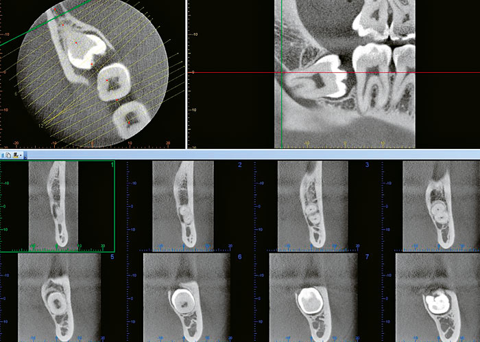
Fig. 6. A curve drawn along the longitudinal axis of a non-erupted lower molar provide cross-sectional images, perpendicular to this curve, yielding detailed information about the relation between the roots of the tooth and the mandibular canal.
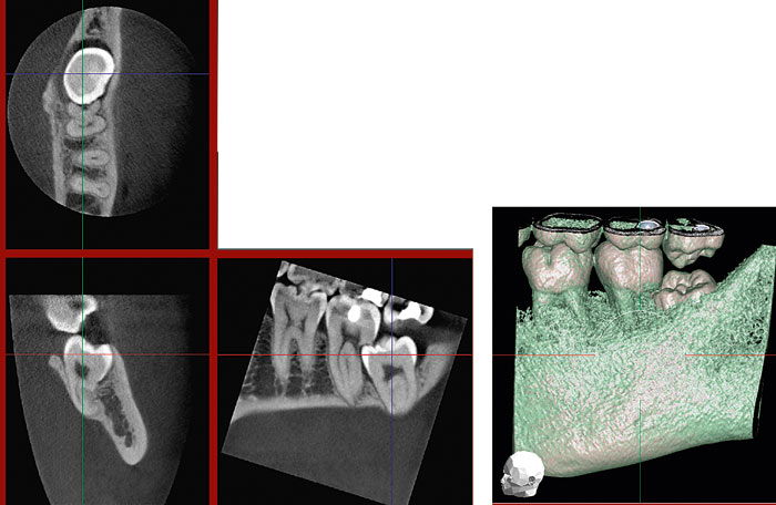
Fig. 7. A non-erupted lower molar has caused extensive resorption of the distal root of the adjacent second molar. A volume-rendered image with some of the thinner, marginal, bone digitally removed shows the position of the third molar underneath the distal part of the crown of the second molar.
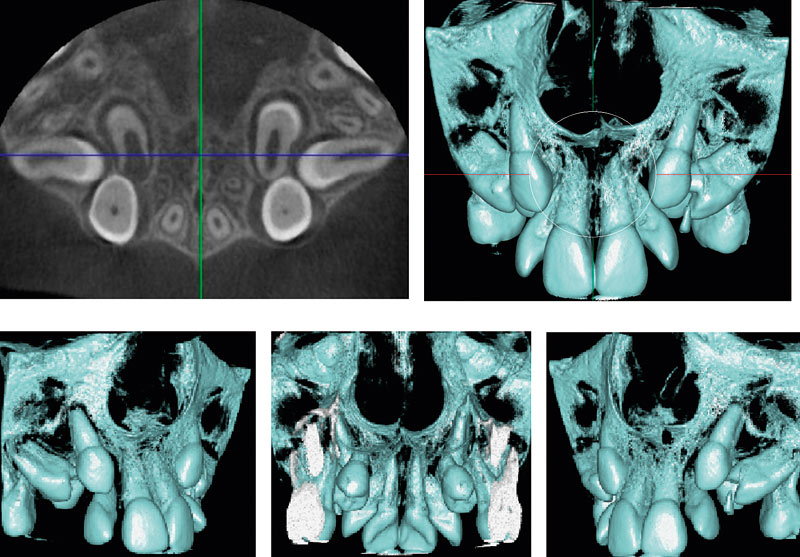
Fig. 8. The axial view of a DVT examination shows non-erupted canines and premolars, the latter in less than normal positions. To fully describe the anatomy of these teeth, and their positions relative to other teeth requires that many new sections are made in different directions. In such a case the volume rendered images provide a quick understanding of the anatomical conditions.
Conventional computed tomography
Trauma
CT is the imaging modality of choice for extensive maxillofacial trauma cases (6). Postoperative CT examination is needed when the extreme precision of reconstruction has to be confirmed, for example in reconstructions of the orbitae. Thin sections in the axial plane, parallel to the Frankfurt Horizontal (FH), are taken. Coronal reformations, orthogonal to the FH plane, are nearly routinely made. Sagittal reconstructions, parallel to the optic nerve, are used when orbital floor fractures are suspected. Images are reconstructed using both soft tissue and bone algorithms and viewed using both soft tissue and bone windowing (6). In particular, fractures of the orbital region (Fig. 9) must be evaluated with soft tissue window and for that reason DVT examinations are not suitable. Three-dimensional (3D) images help to visualize the fractures (Fig. 10).
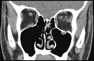
Fig. 9. A coronal CT view shows a small blow-out fracture of the left orbital floor (dashed arrow). The inferior rectal muscle has herniated into the left antrum (big arrow). The small arrow indicates bulbar haematoma.
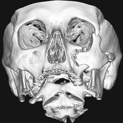
Fig. 10. A 3D image of a dislocated zygomatic fracture on the left side. Fracture lines are indicated with arrows.
CT studies are rarely used to evaluate isolated mandibular fractures. However, CT is of value in the evaluation of complex mandibular – including condylar – fractures (7). DVT should be considered an alternative imaging method. Maxillofacial fractures are often associated with dento-alveolar fractures that should be observed in the CT examination. This is, however, not a method of choice for isolated dento-alveolar traumata. Trauma of the head and the cervical spine often coexist with large maxillofacial fractures. For that reason, where multitrauma or high energy trauma patients are concerned, CT examination of the head and the cervical spine should be done to find out neurosurgically significant lesions.
Tumours, cysts and bone abnormalities
Malignant tumours – In the oral cavity squamous cell carcinoma (SCC) accounts for approximately 90 % of the malignant tumours. Other malignancies include minor salivary gland tumours, lymphomas, and a variety of other rare tumours, including sarcomas. The primary purpose of imaging these lesions is to detect their deep or submucosal extent. In addition, local and distant metastases are evaluated. Staging of primary malignancies of the oral cavity is based on TNM (T = tumour size and its invasion to adjacent structures, N = local metastases and M = distant metastases) system developed by the American Joint Commission on Cancer Staging (8).
At present, CT and MRI are the most commonly used imaging techniques for oral cancer evaluations (9). CT and MRI are used for treatment planning and follow-up studies. CT and MR allow for differentiation of soft tissues and for assessment of the integrity of adjacent bone. CT is very sensitive for detecting small areas of cortical bone invasion (Fig. 11 A). MR is better for evaluating the extent of bone marrow invasion by the tumour. When perineural tumour spread is suspected, for example with adenocystic carcinoma, MR is the imaging modality of choice. Iodine contrast enhanced CT studies are used. The scanning region comprises the base of the skull to the clavicle. Vascular regions of the SCC enhances more than the surrounding tissues (Fig. 11 B). However, contrast enhancement of the SCC is variable, including occasionally non-enhancing necrotic parts of the tumour. Normal soft tissue planes are distorted depending on the size of the tumour.
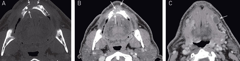
Fig. 11. Gingival squamous cell carcinoma in the anterior region of the mandible. A: Bone window CT image shows the bone destruction (arrows) and B: contrast enhanced soft tissue image shows the soft tissue part of the tumour (arrows). C: A metastatic lymph node with necrosis is visible (arrow) in the submandibular gland level on the left side.
The size, shape, necrosis and extracapsular spread of the lymph nodes are evaluated (Fig. 11 C). Assessment of invasion of vital structures, i.e. common or internal carotid artery, internal jugular vein, the skull base or thoracic inlet, is also indicated. Som et al. have published an imaging-based nodal classification for evaluation of neck metastatic adenopathy (Level I-V) (10). Unfortunately there are no definite size criteria to diagnose metastatic lymph nodes. None of the currently available imaging techniques are able to depict small tumour deposits inside lymph nodes (11). For example ultrasound (US) examination combined with fine needle aspiration (FNA) can be useful for staging (12).
Imaging is an important part of follow-up. The same imaging method is recommended to be used throughout the follow-up, because the changes occurring after surgery and radiotherapy are frequently extensive. Any new lesions are easier to distinguish from changes occurring as a result of treatment. Detailed history data on e.g. the time of surgery, reconstruction and radiotherapy are crucially important for follow-up (13).
Benign (odontogenic) tumours, cysts, bone abnormalities – When evaluating benign tumours, cysts and bone abnormalities with CT, the benefits and disadvantages – radiation dose, costs – of the examination must be carefully evaluated. The use of DVT should be considered. When the visualisation of the soft tissues is crucial, conventional CT, especially with contrast enhancement is recommended. MR is the alternative imaging method. In addition MR is better for evaluation of the bone marrow abnormalities. The contrast-enhanced images are considered to be useful for example differentiating odontogenic cysts, which show rim enhancement, from tumours consisting of solid components.
Neck infections
Neck abscesses are not as common as in the past because of the widespread use of antibiotics. However, dental infections have been reported the most common cause of neck abscesses (14). Salivary gland infections, including stenosis or calculi within the salivary gland ductal systems, upper respiratory infections, trauma or foreign bodies, may be other causative factors. Clinical evaluation and conventional X-rays i.e. panoramic and/or intraoral radiographs usually solve the dental problem and curative treatment can be given. In complicated cases the extent or reason for the infection cannot be evaluated with these methods.
US is the imaging method of choice to evaluate small or localised abscesses. Deeply located abscesses cannot be evaluated with US and contrast enhanced CT examination is indicated.
In CT images an abscess appears as a single or multiloculated low-density area, with or without gas collection. It usually conforms to fascial spaces and demonstrates peripheral rim enhancement in mature abscesses (Fig. 12). Cutaneous and subcutaneous manifestations of infection are typically present i.e. myositis, thickening of the overlying skin, edematous fat and enhancement of the fascial planes. CT has the advantage of better definition of the dimensions and margins of the lesion compared to US. In addition, airway narrowing can be better visualised with CT. CT demonstrates also small calculi and integrity of the bone cortex.
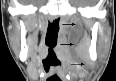
Fig. 12. A coronal contrast enhanced CT image showing a large dentogenic abscess on the left side. The abscess is located in the lingual side of the mandible and extends up to the skull base (arrows).
Treatment can be planned with the help of CT images. In complicated cases CT examination is also useful for monitoring the effect of treatment.
Paranasal sinuses
CT has replaced plain film examinations almost totally in the work-up for inflammatory sinus disease (15). Rhinitis and sinusitis usually coexist and the correct terminology for inflammatory sinus disease is rhinosinusitis (16). The indication of imaging in rhinosinusitis is to confirm the diagnosis, characterize the extent and localisation of the disease and describe anatomical variants in order to select patients that may benefit from sinus surgery (17). Functional endoscopic sinus surgery (FESS) is used to enlarge the natural sinus ostia and passageways of the paranasal sinuses. In cases of fungal sinusitis, mucocele, pyocele or neoplasm MRI provides complementary information to CT (17). Many systemic diseases e.g. Wegener´s granulomatosis, sarcoidosis, cystis fibrosis have sinonasal manifestations and can be evaluated with CT (18).
The use of a low-dose CT examination of paranasal sinuses reduces the effective dose substantially compared to the standard protocol (5).
Implant planning
CT is indicated for implant site assessment in anatomically difficult cases or when extensive implant treatment is planned (19,20).
According to the preliminary lateral scout view, the axial slices are orientated parallel to the inferior border of the mandible for mandibular imaging and parallel to the hard palate for maxillary imaging. CT software programs for example DentaScan (General Electric, Milwaukee, Wis.), 3-D Dental (Columbia Scientific Inc., Columbia, Md.) and ToothPix (Cemax Inc., Fremont, Calif.) can reconstruct desired views i.e. multiple panoramic and true cross-sectional images of the jaws similarly as shown for DVT in Fig. 3 (21).
In addition, bone quantity and quality, in the implantation area are evaluated in the CT scans. Classifications are based upon jaw shape (degree of resorption), bone quality (amount of compact bone) and bone density (22,23). Information about the location of vital structures, such as mandibular canal (24), mental foramen, incisive foramen, maxillary sinuses and nasal cavity can be evaluated.
A plastic stent with radiopaque markers can be used to help for identifying the exact place of the desired implant. The same stent can be placed on the patient at the time of surgery to act as a template for identifying the implant sites. More sophisticated methods for a computed-based transfer are navigation and stereolithographic drill guides. Different soft wares for preoperative planning purposes are available. To reduce radiation doses, low-dose CT examinations are recommended in implant planning (25) In addition DVT offers 3D imaging with a significantly smaller effective dose than conventional CT.
Anomalies, stereolithography
Stereolithography (STL) is a method of organ-model-production based on computed tomography scans which enables the 3D representation of anatomical structures (Fig. 13). Surfaces and internal structures of organs can be produced by polymerization of UV-sensitive liquid resin using a laser beam. Advantages of STL are the representation of complex anatomical structures, high accuracy, and the option to sterilize the models for intraoperative use. Accurate treatment planning is possible with the help of this method. It improves postoperative results, decreases risks and shortens the treatment time (26). Major indications for STL are reconstructive surgery, distraction osteogenesis and previously mentioned dental implantology. Its use is recommended only in selected cases due to high radiation dose and costs (27). Severe anomalies – congenital or acquired – are an indication for the CT examination and the use of STL models.
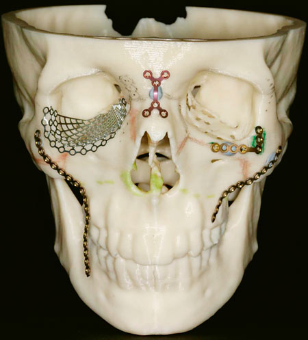
Fig. 13. A stereolithography model produced for treatment planning of a large midfacial squamous cell carcinoma. The model has been used for designing the frameworks needed for the reconstruction.
Temporomandibular joint (TMJ)
CT examinations of the TMJ are suitable for the diagnosis of bony abnormalities including fractures, dislocations, arthritides, ankylosis, neoplasia, and TMJ implants. A decade ago the authors of a position paper of the American Academy of Oral and Maxillofacial Radiology recommended CT for the evaluation of foreign body giant cell reaction to silicon or PTFE sheet implants, suspected tumours, ankylosis and complex facial fractures (7). DVT appears to be both a cost- and dose-effective alternative for conventional CT when diagnosing e.g. erosion and osteophytes of the TMJ (28). Indeed, the diagnostic capabilities of the DVT are not yet established.
English summary
Computed tomography in oral and maxillofacial radiology
Computed tomography (CT) is today frequently used in imaging of the oral and maxillofacial region. Conventional CT was introduced in 1972 and today CT machines are used in all medical X-ray departments. Cone beam computed tomography, also known as digital volume tomography (DVT), was first introduced for imaging of the jaws in the late 1990s. Several machines have been constructed by many manufacturers around the world. Conventional CT might give high radiation doses and one advantage with DVT is that the radiation dose can be reduced substantially. Conventional CT is used for examinations of e.g. facial traumata and tumours, while DVT often is used for examinations of the teeth and jaws. Examples of examinations are preoperative planning of implant treatment, examination of non-erupted teeth with suspicion of resorption of adjacent roots and the temporomandibular joint.
References
1. RCR Working Party. Making the best use of a Department of Clinical Radiology: Guidelines for Doctors (Fourth edition). London: The Royal College of Radiologists; 1998.
2. Strålning – risk och nytta. Broschyr. Swedish Radiation Protection Authority. Nov. 2002. www.ssi.se
3. Scarfe WC, Farman AG, Sukovic P. Clinical applications of cone-beam computed tomography in dental practice. J Can Dent Assoc 2006; 72: 75 – 80.
4. Ludlow JB, Davies-Ludlow LE, Mol A. Dosimetry of recently introduced CBCT units for oral and maxillofacial radiology. In: The 16th International Congress of Dentomaxillofacial Radiology. (Abstract). Beijing: 2007. p.97.
5. Siemund R, Cervin A, Holje G, Svensson C, Forsell Å. Lågdos – DT bättre än vanlig röntgen vid diagnostik av rinosinuit. Läkartidningen 2007; 104: 2955 – 8.
6. Linnau KF, Stanley RB Jr, Hallam DK, Gross JA, Mann FA. Imaging of high-energy midfacial trauma: what the surgeon needs to know. Eur J Radiol 2003; 48: 17 – 32.
7. Brooks SL, Brand JW, Gibbs SJ, Hollender L, Lurie AG, Omnell KÅ, et al. Imaging of the temporomandibular joint. A position paper of the American Academy of Oral and Maxillofacial Radiology. Oral Surg Oral Med Oral Pathol Oral Radiol Endod 1997; 83: 609 – 18.
8. Sobin LH, Wittekind C. Classification of malignant tumours. UICC International Union Against Cancer. 6th ed. New York: Wiley-Liss; 2002.
9. Lenz M, Greess H, Baum M, Dobritz M, Kersting-Sommerhoff B. Oropharynx, oral cavity, floor of the mouth: CT and MRI. Eur J Radiol 2000; 33: 203 – 15.
10. Som PM, Curtin HD, Manusco AA. Imaging-based nodal classification for evaluation of metastatic adenopathy. AJR 2000; 174: 837 – 44.
11. Castelijns JA, van der Brekel MW. Imaging of lymphadenopathy in the neck. Eur Radiol 2002; 12: 727 – 38.
12. Knappe M, Louw M, Gregor RT. Ultrasonograpgy-guided fine needle aspiration for the assessment of cervical metastases. Arch Otolaryngol Head Neck Surg 2000; 126: 1091 – 6.
13. Syrjänen S, Grenman R, Hiiri A, Ojala A, Palin-Palokas T, Soukka T, et al. Päivitetty Käypä hoito –suositus. Suusyöpä. Duodecim 1. päivitys 8.12.2006; p. 1 – 21.
14. Stalfors J, Adielsson A, Ebenfelt A, Nethander G, Westin T. Deep neck space infections remain a surgical challenge. A study of 72 patients. Acta Otolaryngol 2004; 124: 1191 – 6.
15. Ling FT, Kountakis SE. Advances in imaging of the paranasal sinuses. Curr Allergy Asthma Rep 2006; 6: 502 – 7.
16. Fokkens W, Lund V, Mullol J. European position paper on rhinosinusitis and nasal polyps 2007. Rhinol Suppl 2007; 20: 1 – 36.
17. Eggesbø HB. Radiological imaging of inflammatory lesions in the nasal cavity and paranasal sinuses. Eur Radiol 2006; 16: 872 – 88.
18. Alobid I, Guilemany JM, Mullol J. Nasal manifestations of systemic illnesses. Curr Allergy Asthma Rep 2004; 4: 208 – 16.
19. Tyndall DA, Brooks SL. Selection criteria for dental implant site imaging: a position paper of the American Academy of Oral and Maxillofacial radiology. Oral Surg Oral Med Oral Pathol Oral Radiol Endod 2000; 89: 630 – 7.
20. Guerrero ME, Jacobs R, Loubele M, Schutyser F, Suetens P, van Steenberghe D. State-of-the-art on cone beam CT imaging for preoperative planning of implant placement. Clin Oral Investig 2006; 10: 1 – 7.
21. Frederiksen NL. Diagnostic imaging in dental implantology. Oral Surg Oral Med Oral Pathol Oral Radiol Endod 1995; 80: 540 – 54.
22. Lekholm U, Zarb G. Patient selection and preparation. In: Brånemark P-I, Zarb G, Albrektsson T, editors. Tissue-integrated prostheses. Osseointegration in clinical dentistry. Chicago: Quintessence; 1985 p. 199 – 209.
23. Wood MR, Vermilyea SG. A review of selected dental literature on evidence-based treatment planning for dental implants: report of the Committee on Research in Fixed Prosthodontics of the Academy of Fixed Prosthodontics. J Prosthet Dent 2004; 92: 447 – 62.
24. Lindh C, Petersson A, Klinge B. Measurements of distances related to the mandibular canal in radiographs. Clin Oral Impl Res 1995; 6: 96 – 103.
25. Ekestubbe A, Gröndahl K, Ekholm S, Johansson PE, Gröndahl HG. Low-dose tomographic techniques for dental implant planning. Int J Oral Maxillofac Implants 1996; 11: 650 – 9.
26. Bill JS, Reuther JF, Dittmann N, Kübler N, Meier JL, Pistner H, et al. Stereolitography in oral and maxillofacial operation planning. Int J Oral Maxillofac Surg 1995; 24: 98 – 103.
27. Bill JS, Reuther JF. Rechnergestützte Modellbauverfahren zur Planung ausgedehnter Rekonstruktionseingreiffe in Schädelberecih. Mund Kiefer GesichtsChir 2004; 8: 135 – 53.
28. Hussain AM, Packota G, Major PW, Flores-Mir C. Role of different imaging modalities in assessment of temporomandibular joint erosions and osteophytes: a systematic review. Dentomaxillofac Radiol 2008; 37: 63 – 71.
Adresse: Arne Petersson, Department of Oral and Maxillofacial Radiology, Malmö University, S-205 06 Malmö, e-post. Arne.Petersson@mah.se
Artikkelen er fagfellevurdert.
Artikkelen siteres som:
Petersson A, Gröndahl H, Suomalainen A. Computed tomography in oral and maxillofacial radiology. Nor Tannlegeforen Tid. 2009;119:86–93. doi:10.56373/2009-2-3