Anvendelse af røntgencefalometri inden for ortodontien
Forfatter
professor, dr. odont., ph.d. Odontologisk Institut, Det Sundhedsvidenskabelige Fakultet, Københavns Universitet
Den røntgencefalometriske teknik blev introduceret for mere end 75 år siden. I dag anvendes profilrøntgenbilleder rutinemæssigt af specialtandlæger i ortodonti over hele verden ifm. diagnostik, behandlingsplanlægning og follow-up. Denne artikel giver en oversigt over teknikkens udvikling og anvendelse igennem tiden. Derudover gøres der status over teknikkens betydning for den kliniske ortodonti og ortodontisk forskning. Det konkluderes, at til trods for at teknikken i princippet er 2-dimensional, og at der inden for de senere år er udviklet 3-dimensionale teknikker til opmåling af ansigtets bløddele, kæbeskelet og tænder, så vil profilrøntgenbilledet fortsat være et vigtigt hjælpemiddel inden for den kliniske ortodonti i adskillige år fremover. Der gives i den forbindelse nogle anbefalinger til anvendelse ifm. anskaffelse af nyt cefalometrisk røntgenudstyr og software til cefalometrisk analyse.
Inden for ortodontien anvendes røntgencefalometriske optagelser i lateral projektion og panoramarøntgenbilleder rutinemæssigt i forbindelse med diagnostik, behandlingsplanlægning og follow-up (1). Inden for de senere år er der derudover udviklet dels ikke-radiografiske cefalometriske målemetoder (fx 3D digitizer teknik (2) og 3D overfladescanning (3)) dels scanningsmetoder som CBCT (Cone Beam CT scanning)(4,5). Af forskellige årsager har disse teknikker imidlertid endnu ikke vundet større udbredelse (2,6,7), og det ser ud til, at den kliniske ortodonti vil fortsætte med at anvende den røntgencefalometriske teknik i adskillige år fremover. Denne artikel vil alene fokusere på den røntgencefalometriske teknik, mens CBCT scanning vil blive behandlet i en anden artikel i dette tema.
Baggrund
Den røntgencefalometriske teknik udsprang i 1931 af kraniometrien og antropometien. Kraniometrien blev anvendt til præcis opmåling af kranier, mens antropometrien anvendte standardiserede direkte målinger på levende individer. Inden for den kliniske ortodonti var der et behov for en objektiv, kvantitativ og reproducerbar metode til analyse af dentitionens relation til kæberne og kæbernes relation til kraniet over tid, som kunne muliggøre vurdering af ændringer forårsaget af vækst og/eller behandling.
Såvel tyskeren Hofrath (8) som amerikaneren Broadbent (9) udviklede i 1931 røntgencefalometriske apparaturer (cefalometriske units), som til dels muliggjorde dette. Hofraths (8) cefalometriske unit havde et enkelt røntgenrør og kunne alene optage den laterale projektion, mens Broadbents (9) udstyr havde to røntgenkilder og kunne optage såvel den laterale som den frontale cefalometriske projektion. Princippet i den røntgencefalometriske teknik er, at der skal kunne optages standardiserede kranierøntgenbilleder med minimal distorsion og kendt forstørrelse i en præcis og reproducerbar stilling af hovedet (10,11). En cefalometrisk unit består derfor af et imaging system med kendt geometri og af et system til præcis og reproducerbar positionering af patientens hoved (cefalostat) under eksponeringen. Næsten alle eksisterende units arbejder med en stor afstand fra røntgenfokus til cefalostatens centrum og en kort afstand fra cefalostatens centrum til filmplanet med henblik på at reducere såvel billedets distorsion som forstørrelsesgraden mest muligt.
Udvikling af teknikken
Siden den røntgencefalometriske teknik blev introduceret for mere end 75 år siden, er der udviklet mange forskellige cefalometriske units med varierende vægt på billedkvalitet, billedgeometri, typer af mulige projektioner, nøjagtighed af hovedindstilling, pladsbehov og økonomi. Tabel 1 viser nogle af de signifikante trin i udviklingen i den røntgencefalometriske teknik i perioden. Som det fremgår af tabellen, vedrører den tekniske udvikling: (a) Flere mulige projektioner (lateral, frontal, skrå lateral, skrå frontal og aksial projektion) (Fig. 1 – 5); (b) forbedret hovedindstilling med anvendelse af lyskryds eller laserkryds projiceret på ansigt og hoved og gennemlysningssystemer til præcis og reproducerbar hovedindstilling; (c) anvendelse af fast forstørrelsesgrad, som muliggør direkte vækst- og behandlingsanalyse ved overlægning af de longitudinelle serier af billeder optaget over tid; (d) forbedret billedkvalitet og senest (e) digital teknik med mulighed for reduceret røntgendosis til patienten.
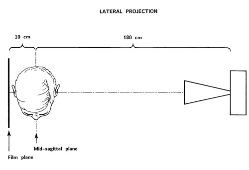
Fig. 1. Den laterale røntgencefalometriske projektion ad modum Björk (14) med faste afstande fra røntgenfokus til hovedets midtsagittal plan og fra midtsagittalplanet til filmplanet. Med de anvendte afstande bliver forstørrelsen af midtsagittalplanet 5,6 %.
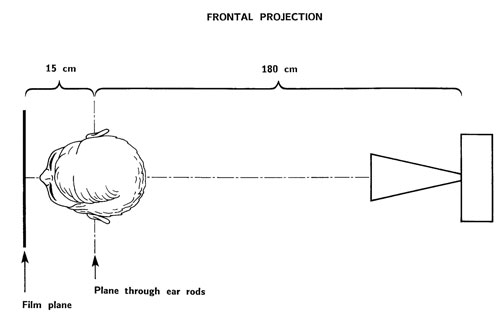
Fig. 2. Den frontale(postero-anteriore) røntgencefalometriske projektion ad modum Björk (14) med faste afstande fra røntgenfokus til planet gennem ørepindene og fra planet gennem ørepindene til filmplanet. Med de anvendte afstande bliver forstørrelsen af planet gennem ørepindene 8,3 %.
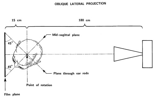
Fig. 3. Den skrå laterale røntgencefalometriske projektion ad modum Margolis (12).
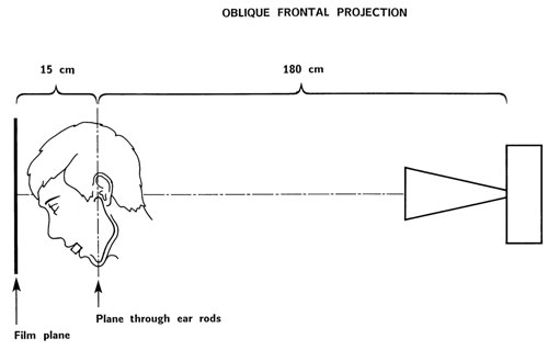
Fig. 4. Den skrå frontale røntgencefalometriske projektion ad modum Björk (19) med faste afstande fra røntgenfokus til planet gennem referencepunkterne condylion (cd) og prognation (pgn) og fra dette plan til filmplanet. Med de anvendte afstande bliver forstørrelsen af planet gennem condylion (cd) og prognation (pgn) 8,3 %.
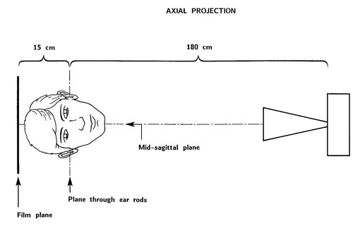
Fig. 5. Den aksiale røntgencefalometriske projektion ad modum Björk (13) med faste afstande fra røntgenfokus til planet gennem ørepindene og fra planet gennem ørepindene til filmen. Med de anvendte afstande bliver forstørrelsen af planet gennem ørepindene 8,3 %.
Referencer |
Trin i udviklingen |
|---|---|
Hofrath (8) |
Lateral projektion |
Broadbent(9) |
Lateral og frontal projektion |
Margolis (12) |
Skrå lateral projektion |
Ortiz & Brodie (13) |
Spædbarnscefalometri; lateral projektion |
Björk (13) |
Aksial projektion; fast afstand fra midtsagittalplanet og planet sv.t. ørepindene til filmen; fast forstørrelse |
Cartright & Harvold (15) |
Høj-kilovolt teknik |
Pruzansky & Lis (16) |
Spædbarnscefalometri; lateral og frontal projektion; sederingsmetode |
Pruzansky (17) |
Spædbarnscefalometri; aksial projektion |
Björk (18) |
Forbedret hovedindstilling med anvendelse af gennemlysning, TV-monitor og et lyskryds projiceret på ansigtet |
Björk (18) |
Cefalometrisk unit bevægelig i vertikal retning til optagelse af individer i stående stilling |
Björk (19) |
Skrå frontal projektion |
Kreiborg et al. (20) |
Spædbarnscefalometri; høj-kilovolt teknik, fast afstand fra midtsagittalplanet og planet sv.t. ørepindene til filmen; fast forstørrelse; forbedret hovedindstilling med lyskryds projiceret på ansigtet; også til den aksiale projektion; simultan optagelse af lateral og frontal projektion |
Jackson et al. (21) |
Digital cefalometri |
Solow & Kreiborg (22) |
Forbedret hovedindstilling med anvendelse af gennemlysning, TV-monitor og seks laserstråler projiceret på ansigt og hoved |
Näslund et al. (23) |
Digital cefalometri med lav stråledosis |
Projektioner og kontrol af hovedindstilling
Som nævnt er der i princippet mulighed for at anvende forskellige røntgencefalometriske projektioner (fx lateral, frontal og aksial projektion), hvilket i princippet skulle give mulighed for en 3-dimensional analyse af den kraniofaciale region. Problemet er imidlertid, at næsten ingen af de udviklede cefalometriske units giver mulighed for en præcis og reproducerbar indstilling af patientens hoved i forbindelse med den frontale og den aksiale projektion. Den ideelle hovedindstilling fremgår af Fig. 6. Fejl i hovedindstillingen i form af frem-tilbage kipning, lateral kipning eller rotation (Fig. 6) introducerer forudsigelige fejl i de forskellige røntgenprojektioner (Tabel 3).
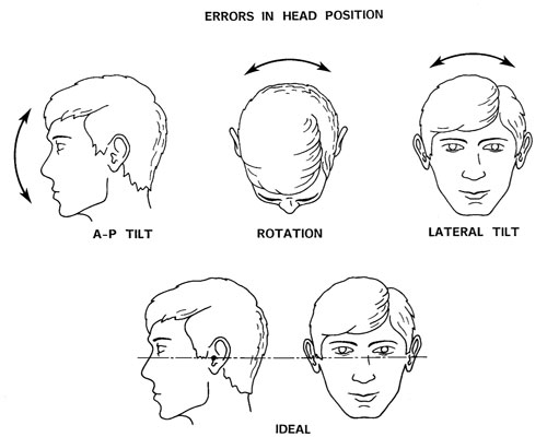
Fig. 6. Den ideale hovedposition i cefalostaten er vist nederst. Mulige fejl i hovedpositionen er vist øverst som: Frem-tilbage kipning, rotation og lateral kipning.
Referencer |
Trin i udviklingen af cefalometrisk analyse |
|---|---|
Brodie (35) |
Justering for forstørrelsen; vækstanalyse med sella-nasion som reference |
Björk (36) |
Fast forstørrelse; direkte vækstanalyse med sella-nasion som reference |
Björk (37) |
Metalimplantater (fiducials) indsat i kæberne mhp. at differentiere mellem displacering og overfladeremodellering af kæberne |
Moorrees & Kean (38) Solow & Tallgren (39) |
Cefalometriske optagelser i naturlig hovedholdning |
Björk (40) |
Vækstanalyse med superimponering på anatomiske strukturer i fossa cranii ant. |
Brown et al. (41) Solow (42) Harris et al. (43) |
Multivariat statistik appliceret til cefalometriske data |
Walker (44)Solow (45) |
Billedbehandling af cefalometriske film |
Walker (44, 46) Ricketts (47) Kreiborg (48) Hermann et al. (24) |
Computeriseret cefalometri; digitalisering af film i lateral, frontal og axial projektion; computermodeller; gennemsnitsplots m.m. |
Hollender et al. (49) Rune et al. (50) |
Stereoskopisk cefalometri med anvendelse af metalimplantater (fiducials) |
Walker & Kowalski (51) Ricketts et al. (52) |
Computeriseret vækst- og behandlingssimulation |
Baumrind et al. (53) |
Stereometrisk cefalometri baseret på parrede co-planar images uden anvendelse af metalimplantater |
Cohen et al. (54) |
Automatisk identifikation af referencepunkter |
Grayson et al. (55) Brown & Abbott (56) |
Referencepunkter med tre koordinater (x, y, z) |
www.tiops.com (57) Donatsky et al. (58) Power et al. (59) |
Direkte vækstanalyse af digitale billeder; prædiktion og simulering af vækst og behandlingseffekt (ortodonti og kæbekirurgi) |
Projektionsfejl forårsaget af fejl i positionering af hovedet |
|||
|---|---|---|---|
Projektion |
A-P kipning |
Lateral kipning |
Rotation |
Lateral |
- |
+ |
+ |
Frontal |
+ |
- |
+ |
Axial |
+ |
+ |
- |
Broadbents (9) cefalometriske unit anvendte to røntgenkilder mhp. simultan optagelse af den laterale og den frontale projektion. Cefalostaten havde ørepinde og næsestøtte. Hovedet blev orienteret i cefalostaten, så Fankfurt horisontalen var parallel med gulvet og med bedst mulig visuel kontrol af hovedets indstilling mht. frem-tilbage kipning, rotation og lateral kipning. Björk (18) udviklede et mere avanceret system til indstilling af hovedet; udover ørepinde og næsestøtte anvendte han et lyskryds projiceret på ansigtet og et gennemlysningssystem. Denne metode førte til en næsten perfekt indstilling af hovedet ved hver optagelse hvad angår den laterale projektion. Men da Björks cefalometriske unit kun anvendte ét røntgenrør, var det nødvendigt at tage patienten ud af cefalostaten, dreje cefalostaten 90 grader og derefter foretage en ny indstilling af hovedet inden optagelsen af den frontale projektion kunne foretages; det samme gjorde sig gældende for den aksiale projektion.
Hovedindstillingen ifm. disse projektioner kunne alene kontrolleres vha. ørepindene og visuel inspektion, og det førte til introduktion af fejl og derved til manglende reproducerbarhed. I forbindelse med konventionel cefalometri med anvendelse af én røntgenkilde, kan det generelt siges, at den frontale og den aksiale projektion er forbundet med en uacceptabel kontrol af hovedindstillingen, mens hovedindstillingen i forbindelse med den laterale projektion er acceptabel, hvis der anvendes ørepinde og et lyskryds projiceret på ansigtet (Tabel 4). Dette er nok den væsentligste forklaring på, at formentlig mere end 95 % af alle optagne røntgencefalometriske billeder er optaget i den laterale projektion.
Projektion |
Kontrol af positionering af hovedet |
||
|---|---|---|---|
A-P kipning |
Lateral kipning |
Rotation |
|
Lateral |
Uden betydning |
Acceptabel |
Acceptabel |
Frontal |
Acceptabel |
Uden betydning |
Ikke acceptabel |
Aksial |
Acceptabel |
Ikke acceptabel |
Uden betydning |
De røntgencefalometriske units, som blev udviklet af Kreiborg et al. (20) og af Solow & Kreiborg (22) med anvendelse af to røntgenkilder og avancerede systemer til præcis hovedindstilling, giver mulighed for seriøs anvendelse af såvel den laterale som den frontale og den aksiale projektion og giver derved mulighed for en form for 3-dimensional analyse af den kraniofaciale region over tid (24,25). Disse units er imidlertid kostbare og pladskrævende prototyper, som ikke finder rutinemæssig anvendelse inden for klinisk ortodonti.
Forstørrelsesproblematik
Broadbents (9) cefalometriske unit anvendte en fast afstand på 5 fod (152,4 cm) fra røntgenfokus til cefalostatens centrum. Filmkassetterne blev skubbet så tæt på ansigtet som muligt for at mindske distorsion og forstørrelse af billedet. Afstanden fra kassetten til cefalostatens centrum kunne derefter aflæses på indbyggede målepinde, som skulle aflæses ved hver optagelse. Forstørrelsen af hovedets midtsagittale plan og planet gennem ørepindene kunne derefter beregnes for det enkelte billede. Senere og simplere cefalometriske units, som baserer sig på Broadbents teknik anvender af pladshensyn kun én røntgenkilde kombineret med en drejelig cefalostat, som nævnt ovenfor; her vurderes forstørrelsen af billedet ved, at der anbringes en 10 cm lang aluminiumslineal i cefalostaten svarende til midtsagittalplanet og planet gennem ørepindene; linealen bliver fotograferet ind på filmen, hvilket muliggør, at der i forbindelse med analysen (målingerne) kan korrigeres for den varierende forstørrelsesgrad. Björk (14) valgte en anden løsning, nemlig faste afstande fra cefalostatens centrum til filmene kombineret med en større afstand fra fokus til cefalostatens centrum (Fig. 1 og 2).
Forstørrelsen af midtsagittalplanet ved den laterale projektion bliver herved altid 5,6 % ((190 cm x 100)/180 cm) (Fig. 1); for planet gennem ørepindene ved den frontale projektion bliver forstørrelsen altid 8,3 % ((195 cm x 100)/180 cm)(Fig. 2). Denne metode muliggør i princippet direkte vækst- og behandlingsanalyse ved overlægning af to eller flere cefalometriske optagelser i lateral og frontal projektion, taget over tid. Som nævnt ovenfor er dette imidlertid i realiteten kun muligt for den laterale projektion pga. problemerne med en præcis og reproducerbar hovedindstilling i forbindelse med den frontale projektion. Et andet problem med den direkte overlægning af longitudinelle cefalometriske optagelser i den frontale projektion af børn i vækst er, at forstørrelsen af de maxillære strukturer formindskes i forbindelse med, at maxillen ved sin fremadvækst ift. basis cranii kommer nærmere på filmplanet (Fig. 7).
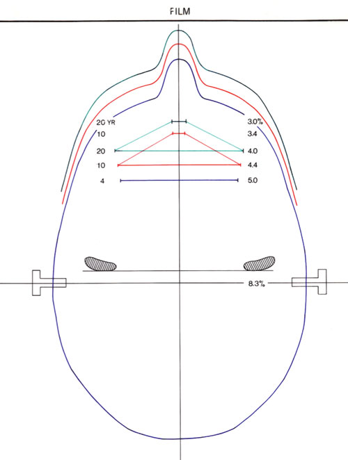
Fig. 7. Illustration af hvordan forstørrelsen af maxillens strukturer på den frontale røntgencefalometriske projektion formindskes ifm. maxillens vækst fremad ift. planet gennem ørepindene. I det viste eksempel reduceres forstørrelsen af maxillens bredde med 1 % (nemlig fra 5,0 % til 4,0 %) fra 4- års alderen til 20-års alderen.
Digital teknik
Digital teknik i forbindelse med røntgencefalometri har i princippet været mulig siden 1985 (21). Adskillige undersøgelser har vist, at den digitale teknik, hvad enten det drejer sig om anvendelse af CCD (charge-coupled device) sensor eller optagelser med anvendelse af SP (storage phosphor) image plade, kan levere billeder af tilstrækkelig kvalitet til røntgencefalometrisk brug (26 – 33). Teknikken giver en række nye muligheder i form af elektronisk billedbehandling til forbedring af kvaliteten og, for nogle systemer, reduceret stråledosis (23). Endelig åbner teknikken for direkte cefalometrisk analyse af billederne på computerskærmen.
Cefalometrisk analyse
Der er igennem årene udviklet en lang række analyser til cefalometrisk analyse; fx Björk analyse, Downs analyse, McNamara analyse, Ricketts analyse, Steiner analyse og Tweed analyse (11,34). Analyserne baserer sig generelt på opmåling af afstande og vinkler baseret på veldefinerede referencepunkter. Udviklingen er gået fra manuelle målinger på røntgenbilleder eller tegninger af røntgenbilleder til digitalisering af punkterne på en film eller en tegning og videre til direkte opmåling på computerskærmen, især i forbindelse med den digitale røntgenteknik (Tabel 2). Softwarepakken TIOPS (57) giver desuden mulighed for direkte vækstanalyse af digitale billeder ad modum Björk og giver derudover mulighed for prædiktion og simulering af kæbevækst samt ortodontisk og ortodontisk/kæbekirurgisk behandlingseffekt.
I de senere år har der, specielt efter indførelsen af digital teknik, været gjort en række forsøg med systemer til automatisk identifikation af cefalometriske referencepunkter mhp. en automatisk morfologisk analyse (27,54,60 – 64). Til trods for en aktiv forskningsindsats på området igennem ca. 25 år findes der imidlertid fortsat ingen egnede computer programmer til automatisk analyse af dentofacial morfologi og vækst eller analyse af behandlingseffekt.
Status og anbefalinger
Hvis man skal gøre status over den røntgencefalometriske tekniks betydning, her godt 75 år efter at den blev introduceret, må man konkludere, at den har haft en enorm succes. Den røntgencefalometriske optagelse i lateral projektion (profilrøntgenbilledet) er i dag et uundværligt hjælpemiddel for de fleste ortodontister i forbindelse med diagnostik, behandlingsplanlægning og follow-up. Metoden anvendes i alle verdensdele, og der er over årene publiceret normative data for dentofacial morfologi og vækst for et stort antal etniske grupper. I Europa er der i næsten alle lande publiceret nationale normative data for såvel børn som voksne. Der er desuden udviklet og afprøvet et relativt stort antal røntgencefalometriske analysemetoder.
Metoden har også fundet stor anvendelse inden for ortodontisk forskning og inden for udforskningen af kongenitte kraniofaciale misdannelser (65). Ifølge databasen PubMed (66) er der alene i første halvår af 2008 publiceret mere end 100 internationale videnskabelige artikler, hvor metoden har været anvendt. I Danmark har den røntgencefalometriske metode- og analyseudvikling været domineret af nu afdøde professor Arne Björk, Tandlægeskolen i København. Björk (14,18) udviklede, som tidligere nævnt, en avanceret cefalometrisk unit karakteriseret ved høj billedkvalitet og præcis og reproducerbar indstilling af hovedet i forbindelse med den laterale projektion samt fast, kendt forstørrelse. Dette muliggjorde hans banebrydende cefalometriske analyser baseret på anvendelse af små metalindikatorer (fiducials) i kæberne (18,36,37,67 – 69). Denne udvikling har haft markant og signifikant indflydelse på såvel udviklingen af den kliniske ortodonti som af ortodontisk og kraniofacial forskning, ikke alene i Danmark, men også internationalt.
Den store udbredelse og anvendelse af den røntgencefalometriske teknik hænger utvivlsomt sammen med, at industrien har udviklet prisbillige, relativt lidt pladskrævende, enkle cefalometriske units, ofte kombineret med muligheden for optagelse af panoramarøntgenbilleder, til rutinemæssig, klinisk ortodontisk brug. Denne udvikling har imidlertid også medvirket til, at det i princippet kun er muligt at optage den laterale cefalometriske projektion med acceptabel reproducerbarhed over tid (se ovenfor). Der har været gjort mange forsøg på at medinddrage den tredje dimension i ortodontisk vækst- og behandlingsanalyse med anvendelse af flere projektioner mhp. at fastlægge referencepunkter med tre koordinater (x, y og z) eller med anvendelse af stereometriske optagelser med eller uden anvendelse af fiducials. Disse tiltag har imidlertid ikke ført til egnede 3-dimensionale analysemetoder til rutinemæssig, ortodontisk brug.
Professor Thomas Graber udtrykte i 2005 på indersiden af omslaget af den seneste udgave af en af de internationalt mest anerkendte lærebøger i ortodonti, nemlig «Orthodontics: Current Principles and Techniques» (70):
«The cover is an artistic interpretation of serial frontal (PA) and lateral (sagittal) cephalometric tracings depicting the Bolton Standard face from Case Western Reserve University. These tracings call attention to the three-dimensional developmental growth and the dentofacial orthopedic challenge at successive ages for each patient. For too long, the PA film has not received adequate consideration by the clinician. We are not only a «generation of profiles», as Sam Weinstein sagely observed many years ago».
Citatet afspejler et klart og erkendt behov for 3-dimensional analyse af den kraniofaciale region indenfor den kliniske ortodonti. Vi må imidlertid se i øjnene, at den røntgencefalometriske teknik, som den har udviklet sig gennem tiden, ikke giver mulighed for optagelse af den frontale projektion med en præcis og reproducerbar hovedindstilling over tid. De fleste units er i stand til at optage den frontale og den skrå frontale projektion, og disse billeder kan analyseres for forekomst af kraniofacial (frontal projektion) og mandibulær (skrå frontal projektion) asymmetri. Det er imidlertid forudsigeligt, at præcis ortodontisk vækst- og behandlingsanalyse af patienter med kraniofacial og/eller mandibulær asymmetri i fremtiden vil blive foretaget ved hjælp af CBCT scanningsmetoden (3,4).
De kommercielt tilgængelige cefalometriske units har således nogle tekniske begrænsninger, som, realistisk vurderet, nok må accepteres, men der er fortsat en række basale tekniske forhold, som bør vurderes og prioriteres før anskaffelsen af nyt udstyr:
(1) Afstanden fra røntgenfokus til filmen skal være størst mulig (mindst 150 cm).
(2) Afstanden fra cefalostatens centrum til filmen skal være fast mhp. fast, kendt forstørrelse.
(3) Cefalostaten skal, udover ørepinde, være forsynet med et lyskryds/laserkryds projiceret på ansigtet til præcis hovedindstilling til den laterale projektion.
(4) Kvaliteten af røntgenbillederne skal være høj med hensyn til kontrast og skarphed.
Kombinationen af fast forstørrelse, præcis og reproducerbar hovedindstilling med minimal distorsion af billederne og høj billedkvalitet er en forudsætning for at anvende Björks metode til analyse af dentofacial vækst og behandlingsændringer med direkte overlægning af billederne på stabile anatomiske strukturer i basis cranii, maxilla og mandibula (68,69).
Med anvendelse af digital imaging teknik er der mulighed for at reducere stråledosis og foretage elektronisk post-processering af billederne for at forbedre billedkvaliteten. Den digitale teknik giver desuden den fordel, at man kan foretage cefalometrisk analyse direkte på computerskærmen med anvendelse af én af de mange tilgængelige softwarepakker på markedet. For de specialtandlæger i ortodonti, som anvender Björks (68,69) analysemetode, vil TIOPS (57) være et oplagt valg.
English summary
Kreiborg S.
Craniofacial imaging in orthodontics
24 – 30.
The roentgencephalometric technique was developed more than 75 years ago by researchers looking for a method for objective, quantitative and reproducible analysis of the relation between the dentition and the jaws and the relation between the jaws and the cranium – over time. Today, cephalometric radiographs in the lateral projection are routinely used worldwide by orthodontists for diagnostics, treatment planning and follow-up. Several other cephalometric projections have been suggested to include the third dimension, but with limited success. However, although the technique, in principle, is limited to two dimensions, it must be anticipated that it will still be in routine use for several years to come.
This review deals with the development of the technique since its introduction and the development of cephalometric analyses. Furthermore, the article summarizes the current application of the technique within clinical orthodontics, recognizing its limitations.
Finally, some recommendations are given related to the purchase of new equipment and software for cephalometric analysis.
Litteratur
Fullstendig litteraturliste er tilgjengelig på Internett – se www.tannlegetidende.no, Tidende nr. 1, 2009 og kan for øvrig fås ved henvendelse til forfatteren.
1. White SC, Pharoah MJ. Oral Radiology. Principles and interpretation. 5th edition St. Louis: Mosby; , 2004.
2. Syriopoulos K, Velders XL, Sanderink GC, van der Stelt PF. Sensitometric and clinical evaluation of a new F-speed dental X-ray film. Dentomaxillofac Radiol 2001; 30: 40 – 4.
3. Wenzel A, Sewerin I. Stråledoser, stråleskader, strålehygiejne. 2. udgave, Munksgaard; 2005.
4. Wenzel A, Møystad A. Decision criteria and characteristics of Norwegian general dental practitioners selecting digital radiography. Dentomaxillofac Radiol 2001; 30: 197 – 202.
5. Tsuchida R, Araki K, Endo A, Funahashi I, Okano T. Physical properties and ease of operation of a wireless intraoral x-ray sensor. Oral Surg Oral Med Oral Pathol Oral Radiol Endod 2005; 100: 603 – 8.
6. Gröndahl H-G, Wenzel A, Borg E, Tammisalo E. An image plate system for digital intraoral radiography – The Digora. Dent Update 1996; 23: 334 – 7.
7. Wenzel A. Effect of varying gray-scale resolution on detectability of bone lesions in intraoral radiographs digitized for teletransmission. Scand J Dent Res 1987; 95: 483 – 92.
8. Berkhout WER, Verheij JG, Syriopoulos K, Li G, Sanderink GC, van der Stelt PF. Detection of proximal caries with high-resolution and standard resolution digital radiographic systems. Dentomaxillofac Radiol 2007; 36: 204 – 10.
9. Wenzel A, Haiter-Neto F, Gotfredsen E. Influence of spatial resolution and bit depth on detection of small caries lesions with digital receptors. Oral Surg Oral Med Oral Pathol Oral Radiol Endod 2007; 103: 418 – 22.
10. Heo MS, Han DH, An BM, Huh KN, Yi WJ, Lee SS, et al. Effect of ambient light and bit depth of digital radiographs on observer performance in determination of endodontic file position. Oral Surg Oral Med Oral Pathol Oral Radiol Endod, 2008; 105: 239 – 44.
11. Wakoh M, Farman AG, Scarfe WC, Kelly MS, Kuroyanagi K. Perceptibility of defects in an aluminum test object: a comparison of the RVG-S and first generation VIXA systems with and without added niobium filtration. Dentomaxillofac Radiol 1995; 24: 211 – 4.
12. Borg E, Gröndahl H G. On the dynamic range of different x ray photon detectors in intra-oral radiography. Dentomaxillofac Radiol 1996; 25: 82 – 8.
13. Borg E, Attaelmanan AG, Gröndahl HG. Image plate systems differ in physical performance. Oral Surg Oral Med Oral Pathol Oral Radiol Endod 2000; 89: 118 – 24.
14. Berkhout WER, Beuger DA, Sanderink GCH, van der Stelt PF. The dynamic range of digital radiographic systems: dose reduction or risk of overexposure? Dentomaxillofac Radiol 2000; 33: 1 – 5.
15. Farman TT, Farman AG. A comparison of 18 different x-ray detectors currently used in dentistry. Oral Surg Oral Med Oral Pathol Oral Radiol Endod 2005; 99: 485 – 9.
16. Attaelmanan AG, Borg E, Gröndahl HG. Signal-to-noise ratios of 6 intraoral digital sensors. Oral Surg Oral Med Oral Pathol Oral Radiol Endod 2001; 91: 611 – 5.
17. Wenzel A, Søbye I, Andersen M, Erlendsson T. Intraorale digitale receptorers dynamikområde og evne til at fremstille et lavkontrastobjekt. Tandlægebladet 2007; 14: 1080 – 6.
18. Skov SJ, Sewerin I. Konstanskontrol af fremkaldeprocessen ved brug af dentalrøntgenanlæg med spændinger til og med 70 kV. Tandlægebladet 2000; 104: 250 – 4.
19. Borch V, Østergaard M, Gotfredsen E, Wenzel A. Identifikation af billedfejl, der er særlige for røntgenoptagelse med digitale intraorale receptorer. Tandlægebladet 2008, 112: 720 – 31.
20. Bedard A, Davies TD, Angelopoulos C. Storage phosphor plates: How durable are they as a digital radiographic system? J Comtemp Dent Pract 2004; 2: 57 – 69.
21. Molander B, Gröndahl H-G. Durability of storage phosphor plates. Abstract 44, Congress of Dentomaxillofacial Radiology. Beijing: China; 2007.
22. Ramamurthy R, Canning CF, Scheetz JP, Farman AG. Time and motion study: a comparison of two photostimulable phosphor imaging systems used in dentistry. Dentomaxillofac Radiol 2006; 35: 315 – 8.
23. Aknediz BG, Gröndahl HG, Kose T. Effect of scanning of storage phosphor plates. Oral Surg Oral Med Oral Pathol Oral Radiol Endod 2005; 99: 603 – 7.
24. Aknediz BG, Gröndahl HG. Degradation of storage phosphor images due to scanning delay. Dentomaxillofac Radiol 2006; 35: 74 – 7.
25. Ang DB, Angelopoulos C, Katz JO. How does signal fade on photo-stimulable storage phosphor imaging plates when scanned with a delay and what is the effect on image quality? Oral Surg Oral Med Oral Pathol Oral Radiol Endod 2006; 102: 673 – 9.
26. Martins MGBQ, Whaites EJ, Ambrosano GMB, Haiter-Neto F. What happens if you delay scanning Digora phosphor storage plates (PSPs) for up 4 hours? Dentomaxillofac Radiol 2006; 35: 143 – 6.
27. Lopes SL, Cruz AD, Ferreira RI, Bóscolo FN, Almeida SM. Image quality in partially erased DenOptix® storage phosphor plates. Braz Oral Res 2008; 22: 78 – 83.
28. Berkhout WER, Sanderink GCH, van der Stelt PF. A comparison of digital and film radiography in Dutch dental practices assessed by questionnaire. Dentomaxillofac Radiol 2002; 31: 93 – 9.
29. Wenzel A, Møystad A. Experience of Norwegian general dental practitioners with solid state and storage phosphor detectors. Dentomaxillofac Radiol 2001; 30: 203 – 8.
30. Hellén-Halme K, Rohlin M, Petersson A. Dental digital radiography: A survey of quality aspects. Swed Dent J 2005; 29: 81 – 7.
31. Bahrami G, Hagstrøm C, Wenzel A. Bitewing examination with four digital receptors. Dentomaxillofac Radiol 2003; 32: 317 – 21.
32. Wenzel A, Frandsen E, Hintze H. Patient discomfort and cross-infection control in bitewing examination with a storage phosphor plate and a CCD-based sensor. J Dent 1999; 27: 243 – 6.
33. Matzen LH, Christensen J, Wenzel A. Patient discomfort and retakes with periapical radiography of mandibular third molars using digital receptors and film. Oral Surg Oral Med Oral Pathol Oral Radiol Endod 2008; accepted for publication.
34. Hellén-Halme K, Johansson PM, Håkansson J, Petersson A. Image quality of digital and film radiographs sent to the Dental Insurance Office in Sweden for treatment approval. Swed Dent J 2004; 28: 77 – 84.
35. Horner K, Shearer AC, Walker A, Wilson NHF. RadioVisioGraphy: An initial evaluation. Br Dent J 1990; 168: 244 – 8.
36. Versteeg CH, Sanderink GCH, van Ginkel FC, van der Stelt PF. An evaluation of periapical radiography with a charge-coupled device. Dentomaxillofac Radiol 1998; 27: 97 – 101.
37. Gonzalez L, Moro J. Patient radiation dose management in dental facilities according to the x-ray focal distance and the image receptor type. Dentomaxillofac Radiol 2007; 36: 282 – 4.
38. Kaeppler G, Dietz K, Herz K, Reinert S. Factors influencing the absorbed dose in intraoral radiography. Dentomaxillofac Radiol 2007; 36: 506 – 13.
39. Haiter-Neto F, Pontual A, Frydenberg M, Wenzel A. A comparison of older and newer versions of intraoral digital radiography systems. Diagnosing noncavitated proximal carious lesions. JADA 2007; 138: 1353 – 9.
40. Wenzel A, Hansen J. Radiation dose associated with intraoral digital receptors and F-speed film. Oral Radiol 2008; submitted.
41. Berkhout WER, Sanderink GCH, van der Stelt PF. Does digital radiography increase the number of intraoral radiographs? A questionnaire study of Dutch dental practices. Dentomaxillofac Radiol 2003; 32: 124 – 7.
42. Negron W, Mauriello SM, Peterson CA, Arnold R. Cross-contamination of the PSP sensor in a preclinical setting. J Dent Hyg 2005; 79: 1 – 10.
43. Ludlow JB, Abreu Jr. M. Performance of film, desktop monitor and laptop display in caries detection. Dentomaxillofac Radiol 1999; 28: 26 – 30.
44. Wenzel A, Isidor S, Faaborg-Andersen M, Hintze H, Kirkevang L-L, Haiter-Neto F. Effect of monitor quality on detection of approximal caries lesions in digital radiographs. Abstract no. 44, 11th Congress of the European Academy of Dento-maxillo-facial Radiology; 2008.
45. Hellén-Halme K, Nilsson M, Petersson A. Effect of different monitors on detection of approximal caries in digital radiographs. Abstract no. 68, 11th Congress of the European Academy of Dento-maxillo-facial Radiology; 2008.
46. Hellén-Halme K, Nilsson M, Petersson A. Digital radiography in general dental practice: a field study. Dentomaxillofac Radiol 2007; 36: 249 – 55.
47. Hellén-Halme K, Petersson A, Warfvinge G, Nilsson M. Effect of ambient light and monitor brightness and contrast settings on the detection of approximal caries in digital radiographs: an in vitro study. Dentomaxillofac Radiol 2008; 37: 380 – 4.
48. Kutcher MJ, Kalathingal S, Ludlow JB, Abreu M Jr, Platin E. The effect of lighting conditions on caries interpretation with a laptop computer in a clinical setting. Oral Surg Oral Med Oral Pathol Oral Radiol Endod 2006; 102: 537 – 43.
49. Sakurai T, Matsumoto Y, Onoyama K, Kawamata R, Kashima I. Image quality of film transparency printer output of digital dental radiographs. Oral Surg Oral Med Oral Pathol Oral Radiol Endod 2005; 99: 490 – 5.
50. Wenzel A, Gröndahl H-G. Direct digital radiography in the dental office. Int Dent J 1995; 45: 27 – 34.
51. Wenzel A. Matters to consider when implementing direct digital radiography in the dental office. Int J Comput Dent 1999; 2: 269 – 90.
52. Wenzel A. Direkte digital røntgenteknik på tandklinikken. Tandlægebladet 2000; 4: 184 – 96.
53. van der Stelt PF. Filmless imaging: the uses of digital radiography in dental practice. J Am Dent Assoc 2005; 136: 1379 – 87.
54. Petrikowski CG. Introducing digital radiography in the dental office: an overview. J Can Dent Assoc 2005; 71: p. 651.
55. Wenzel A. Digital radiography and caries diagnosis. A review. Dentomaxillofac Radiol 1998; 27: 3 – 11.
56. Wenzel A. Digital imaging for dental caries. Dent Clin North Am 2000; 44: 319 – 38.
57. Wenzel A, Gotfredsen E. Røntgenundersøgelse med digitale systemer. Tandlægebladet 2004; 12: 1024 – 30.
58. Wenzel A. A review of dentists’ use of digital radiography and caries diagnosis with digital systems. Dentomaxillofac Radiol 2006; 35: 307 – 14.
59. Williamson GF. Digital radiography: considerations for pediatric dentistry. Pract Proced Aesthet Dent 2005; 17: 556,558.
60. Nair MK, Nair UP. Digital and advanced imaging in endodontics: a review. J Endod 2007; 33: 1 – 6.
61. Wenzel A, Gotfredsen E. Digital radiography for the orthodontist. Am J Orthod Dentofacial Orthop 2002; 121: 231 – 5.
62. Alkurt MT, Peker I, Bala O, Altunkaynak B. In vitro comparison of four dental x-ray films and direct digital radiography for proximal caries detection. Oper Dent 2007; 32: 504 – 9.
63. Castro VM, Katz JO, Hardman PK, Glaros AG, Spencer P. In vitro comparison of conventional film and direct digital imaging in the detection of approximal caries. Dentomaxillofac Radiol 2007; 36: 138 – 42.
64. Haiter-Neto F, Pontual A, Frydenberg M, Wenzel A. Detection of non-cavitated approximal caries lesions in digital images from seven solid-state receptors with particular focus on task-specific enhancement filters. An ex vivo study in human teeth. Clin Oral Invest 2008; 12: 217 – 23.
65. Wenzel A, Haiter-Neto F, Gotfredsen E. Risk factors for a false positive test outcome in diagnosis of caries in approximal surfaces: impact of radiographic modality and observer characteristics. Caries Res 2007; 41: 170 – 6.
66. Orhan K, Sogur E, Baksi BG, Paksoy CS, Durutürk AM, Büyükkarakaya A, et al. The influence of kilovoltage variation on the diagnosis of occlusal caries in deciduous teeth: comparison of film and digital radiography. Abstract no. 17, 11th Congress of the European Academy of Dento-maxillo-facial Radiology; 2008.
67. Peker I, Alkurt MT, Altunkaynak B. Film tomography compared with film and digital bitewing radiography for proximal caries detection. Dentomaxillofac Radiol 2007; 36: 495 – 9.
68. Haiter-Neto F, Wenzel A, Gotfredsen E. Diagnostic accuracy of cone beam computed tomography scans compared with intraoral image modalities for detection of caries lesions. Dentomaxillofac Radiol 2008; 37: 18 – 22.
69. Woolhiser GA, Brand JW, Hoen MM, Geist JR, Pikula AA, Pink FE. Accuracy of film-based, digital, and enhanced digital images for endodontic length determination. Oral Surg Oral Med Oral Pathol Oral Radiol Endod 2005; 99: 499 – 504.
70. Radel RT, Goodell GG, McClanahan SB, Cohen ME. In vitro radiographic determination of distances from working length files to root ends comparing Kodak RVG 6000, Schick CDR, and Kodak Insight film. J Endod 2006; 32: 566 – 8.
71. Ramamurthy R, Scheetz JP, Clark SJ, Farman AG. Effect of imaging system and exposure on accurate detection of the second mesio-buccal canal in maxillary molar teeth. Oral Surg Oral Med Oral Pathol Oral Radiol Endod 2006; 102: 796 – 802.
72. Kosibowornchai S, Hanwachirapong D, Somsopon R, Pirmsinthavee S, Sooksuntisakoonchai N. Ex vivo comparison of digital images with conventional radiographs for detection of simulated voids in root canal filling material. Int Endod 2006; 39: 287 – 92.
73. Pecoraro M, Azadivatan-le Janal M, Khocht A. Comparison of observer reliability in assessing alveolar bone height on direct digital and conventional radiographs. Dentomaxillofac Radiol 2005; 34: 279 – 84.
74. Khocht A, Janal M, Harasty L, Chang KM. Comparison of direct digital and conventional intraoral radiographs in detecting alveolar bone loss. J Am Dent Assoc 2003; 134: 1468 – 75.
75. Jorgenson T, Masood F, Beckerley JM, Burgin C, Parker DE. Comparison of two imaging modalities: F-speed film and digital images for detection of osseous defects in patiens with interdental vertical bone defects. Dentomaxillofac Radiol 2007; 36: 500 – 5.
76. Mörner-Svalling AC, Tronje G, Andersson LG, Welander U. Comparison of the diagnostic potential of direct digital and conventional radiography in the evaluation of peri-implant conditions. Clin Oral Implants Res 2003; 14: 714 – 9.
77. Kavadella A, Karayiannis A, Nicopoulou-Karayianni K. Detectability of experimental peri-implant cancellous bone lesions using conventional and direct digital radiography. Aust Dent J 2006; 51: 180 – 6.
78. Folk RB, Thorpe JR, McClanahan SB, Johnson JD, Strother JM. Comparison of two different direct digital radiography systems for the ability to detect artificially prepared periapical lesions. J Endod 2005; 31: 304 – 6.
79. Wenzel A, Kirkevang L-L. High resolution charge-coupled device sensor vs. medium resolution photostimulable phosphor plate digital receptors for detection of root fractures in vitro. Dent Traumatol 2005; 21: 32 – 5.
80. Tsesis I, Kamburoglu K, Katz A, Tamse A, Kaffe I, Kfir A. Comparison of digital with conventional radiography in detection of vertical root fractures in endodontically treated maxillary premolars: an ex vivo study. Oral Surg Oral Med Oral Pathol Oral Radiol Endod 2008; Epub.
81. Baksi BG, Ermis RB. Comparison of conventional and digital radiography for radiometric differentiation of dental cements. Quintessence Int 2007; 38: e532 – 6.
82. Sabbagh J, Vreven J, Leloup G. Radiopacity of resin-based materials in film radiographs and storage phosphor plate (Digora). Oper Dent 2004; 29: 677 – 84.
83. Nomoto R, Mishima A, Kobayashi K, McCabe JF, Darvell BW, Watts DC, Momoi Y, Hirano S. Quantitative determination of radio-opacity: equivalence of digital and film x-ray systems. Dent Mater 2008; 24: 141 – 7.
84. Scaf G, Sakakura CE, Kalil PF, Dearo de Morais JA, Loffredo LC, Wenzel A. Comparison of simulated periodontal bone defect depth measured in digital radiographs in dedicated and non-dedicated software systems. Dentomaxillofac Radiol 2006; 35: 422 – 5.
85. Goodarzi Pour D, Razmi H, Jabedar Maralani S, Zeighami S. New software: comparison three software programs for root canal length measurement. Dentomaxillofac Radiol 2008; 37: 228 – 31.
86. Hintze H. Diagnostic accuracy of two software modalities for detection of caries lesions in digital radiographs from four dental systems. Dentomaxillofac Radiol 2006; 35: 78 – 82.
87. Schulte AG, Wittchen A, Stachniss V, Jacquet W, Bottenberg P. Approximal caries diagnosis after data import from different digital radiography systems: interobserver agreement and comparison to histological hard-tissue sections. Caries Res 2008; 42: 57 – 61.
88. Gotfredsen E, Wenzel A, Gröndahl H-G. Observers" use of image enhancement in assessing caries in radiographs taken by four intraoral digital systems. Dentomaxillofac Radiol 1996; 25: 34 – 8.
89. Wenzel A, Kirkevang L-L. Students’ attitudes to digital radiography and measurement accuracy of two digital systems in connection with root canal treatment. Eur J Dent Educ 2004; 8: 167 – 71.
90. Li G, van der Stelt PF, Verheij JG, Speller R, Galbiati A, Psomadellis F, et al. End-user survey for digital sensor characteristics: a pilot questionnaire study. Dentomaxillofac Radiol 2006; 35: 147 – 51.
91. Kosibowornchai S, Basiw M, Promwang Y, Moragorn H, Sooksuntisakoonchai N. Accuracy of diagnosing occlusal caries using enhanced digital images. Dentomaxillofac Radiol 2004; 33: 236 – 40.
92. de Araujo EA, Castilho JC, Medici Filho E, de Moraes ME. Comparison of direct digital and conventional imaging with Ekta Speed Plus and Insight films for the detection of approximal caries. Am J Dent 2005; 18: 241 – 4.
93. Koob A, Sanden E, Hassfeld S, Staehle HJ, Eickholz P. Effect of digital filtering on the measurement of proximal caries under different exposure conditions. Am J Dent 2004; 17: 388 – 93.
94. Haak R, Wicht MJ. Grey-scale reversed radiographic display in the detection of approximal caries. J Dent 2005; 33: 65 – 71.
95. Li G, Engström PE, Welander U. Measurement accuracy of marginal bone level in digital radiographs with and without color coding. Acta Odontol Scand 2007; 65: 254 – 8.
96. Li G, Sanderink GC, Welander U, McDavid WD, Näsström K. Evaluation of endodontic files in digital radiographs before and after employing three image processing algorithms. Dentomaxillofac Radiol 2004; 33: 6 – 11.
97. Kal BI, Baksi BG, Dündar N, Sen BH. Effect of various processing algorithms on the measurement accuracy of endodontic file length. Oral Surg Oral Med Oral Pathol Oral Radiol Endod 2007; 103: 280 – 4.
98. Møystad A, Svanaes DB, van der Stelt PF, Gröndahl HG, Wenzel A, van Ginkel FC, et al. Comparison of standard and task-specific enhancement of Digora storage phosphor images for approximal caries diagnosis. Dentomaxillofac Radiol 2003; 32: 390 – 6.
99. Li G, Sanderink GC, Berkhout WE, Syriopoulos K, van der Stelt PF. Detection of proximal caries in vitro using standard and task-specific enhanced images from a storage phosphor plate system. Caries Res 2007; 41: 231 – 4.
100. Seneadza V, Koob A, Kaltschmitt J, Staehle HJ, Duwenhoegger J, Eickholz P. Digital enhancement of radiographs for assessment of interproximal dental caries. Dentomaxillofac Radiol 2008; 37: 142 – 8.
101. Wenzel A. Computerautomatiserede diagnostiske støttesystemer. Tandlægebladet 1999; 103: 180 – 6.
102. Wenzel A. Computer-automated caries detection in digital bitewings: Consistency of a program and its influence on observer agreement. Caries Res 2001; 35: 12 – 20.
103. Wenzel A, Hintze H, Kold LM, Kold S. Accuracy of computer-automated caries detection in digital radiographs compared with human observers. Eur J Oral Sci 2002; 110: 199 – 203.
104. Güneri P, Akdeniz BG. Fraudulent management of digital endodontic images. Int Endod J 2004; 37: 214 – 20.
105. Calberson FL, Hommez GM, de Moor RJ. Fraudulent use of digital radiography: methods to detect and protect digital radiographs. J Endod 2008; 34: 530 – 6.
106. Gotfredsen E, Wenzel A. Image compression in storing and communicating digital radiographs. Int J Comput Dent 2001; 4: 273 – 9.
107. Wenzel A, Gotfredsen E, Borg E, Gröndahl H-G. Impact of lossy image compression (JPEG) on accuracy of caries detection in digital images taken with a storage phosphor system. Oral Surg Oral Med Oral Pathol Oral Radiol Endod 1996; 81: 351 – 5.
108. Koenig L, Parks E, Analoui M, Eckert G. The impact of image compression on diagnostic quality of digital images for detection of chemically-induced periapical lesions. Dentomaxillofac Radiol 2004; 33: 37 – 43.
109. Fidler A, Likar B, Skaleric U. Lossy JPEG compression: easy to compress, hard to compare. Dentomaxillofac Radiol 2006; 35: 67 – 73.
110. Fidler A, Skaleric U, Likar B. The effect of image content on detail preservation and file size reduction in lossy compression. Dentomaxillofac Radiol 2007; 36: 387 – 92.
1. Sarver DM, Proffit WR. Special considerations in diagnosis and treatment planning. In: Graber TM, Vanarsdall RL, Vig KWL, editors. Orthodontics: current priciples and techniques. St. Louis: Elsevier Mosby; 2005. p. 24.
2. Tsang KHS, Cooke MS. Comparison of cephalometric analysis using a non-radiographic sonic digitizer (DigiGraph Workstation) with conventional radiography. Eur J Orthod 1999; 21: 1 – 13.
3. Weinberg SM, Naidoo S, Govier DP, Martin RA, Kane AA, Marazita ML. Anthropometric precision and accuracy of digital three-dimensional photogrammetry: comparing the Genex and 3dMD imaging systems with one another and with direct anthropometry. J Craniofac Surg 2006; 17: 477 – 83.
4. Mah JK, Hatcher D. Craniofacial imaging in orthodontics. In: Graber TM, Vanarsdall RL, Vig KWL, editors. Orthodontics: current principles and techniques. St. Louis: Elsevier Mosby; 2005. p. 71 – 100.
5. Swennen GRJ, Schutyser F, Hausamen J-E. Three-dimensional cephalometry. A color atlas and manual. Berlin: Springer Verlag; 2006.
6. Chan HJ, Woods M, Stella D. Three dimensional computed craniofacial tomography (3D-CT): potential uses and limitations. Aust Orthod J 2007; 23: 55 – 64.
7. Silva MA, Wolf U, Heinicke F, Bumann A, Visser H, Hirsch E. Cone-beam computed tomography for routine orthodontic treatment planning: a radiation dose evaluation. Am J Orthod Dentofacial Orthop 2008; 133: 640.e1 – 5.
8. Hofrath H. Die Bedeutung der Röntgenfern- und Abstandaufnahme für die Diagnostik der Kieferanomalien. Fortschr Orthod 1931; 1: 232 – 58.
9. Broadbent BH. A new X-ray technique and its application to orthodontia. Angle Orthod 1931; 1: 45 – 66.
10. Broadbent BH Sr, Broadbent BH Jr, Golden WH. Bolton standards of dentofacial developmental growth. St. Louis: The C.V. Mosby Company, 1975.
11. Jacobson A, Jacobson RL, editors. Radiographic cephalometry. From basics to 3-D imaging. 2nd edition. Chicago: Quintessence; 2006.
12. Margolis HI. Standardized x-ray cephalographics. Am J Orthod Oral Surg 1940; 26: 725 – 40.
13. Ortiz MH, Brodie AG. On the growth of the human head from birth to the third month of life. Anat Rec 1949; 103: 311 – 33.
14. Björk A. Some biological aspects of prognathism and occlusion of the teeth. Angle Orthod 1951; 21: 3 – 27.
15. Cartright LJ, Harvold EP. Improved radiographic results in cephalometry through the use of high kilovoltage. Can Dent Assoc J 1954; 20: 260 – 3.
16. Pruzansky S, Lis EF. Cephalometric roentgenography of infants: sedation instrumentation, and research. Am J Orthod 1954; 51: 159 – 86.
17. Pruzansky S. Is roentgencephalometry being fully exploited as an instrument for clinical investigation? Dent Clin North America. Philadelphia: WB Saunders Company; 1966. p. 211 – 7.
18. Björk A. The use of metallic implants in the study of facial growth in children. Am J Phys Anthropol 1968; 29: 243 – 54.
19. Björk A. Kæbernes relationer til det øvrige kranium. In: Lundström A, editor. Nordisk lärobok i ortodonti. Stockholm: Sveriges Tandläkarforbunds Förlagsförening; 1971. p. 163.
20. Kreiborg S, Dahl E, Prydsø U. A unit for infant roentgencephalometry. Dentomaxillofac Radiol 1977; 6: 29 – 33.
21. Jackson PH, Dickson GC, Birnie DJ. Digital image processing of cephalometric radiographs: a preliminary report. Br J Orthod 1985; 12: 122 – 32.
22. Solow B, Kreiborg S. A cephalometric unit for research and hospital environments. Eur J Orthod 1988; 10: 346 – 52.
23. Näslund EB, Møystad A, Larheim TA, Øgaard B, Kruger M. Cephalometric analysis with digital storage phosphor images: extreme low-exposure images with and without postprocessing noise reduction. Am J Orthod Dentofacial Orthop 2003; 124: 190 – 7.
24. Hermann NV, Jensen BL, Dahl E, Darvann TA, Kreiborg S. A method for three projection infant cephalometry. Cleft Palate Craniofac J 2001; 38: 299 – 316.
25. Kreiborg S, Hermann NV, Darvann TA. Characteristics of facial morphology and growth in infants with clefts. In: Berkowitz S, editor. Cleft lip and palate. Diagnosis, and management. 2nd ed. Berlin Heidelberg: Springer-Verlag; 2006. p. 225 – 35.
26. Scutellari PN, Orzincolo C, Verna C, Vincenzi E, Licci R, Vita F. Cephalometry and digital radiography. Technical note. Radiol Med 1993; 86: 899 – 903.
27. Forsyth DB, Davies DN. Assessment of an automated cephalometric analysis system. Eur J Orthod 1996; 18: 471 – 8.
28. Forsyth DB, Shaw WC, Richmond S, Roberts CT. Digital imaging of cephalometric radiographs, part 2: image quality. Angle Orthod 1996; 66: 43 – 50.
29. Gotfredsen E, Kragskov J, Wenzel A. Development of a system for craniofacial analysis from monitor-displayed digital images. Dentomaxillofac Radiol 1999; 28: 123 – 6.
30. Moore WS. Dental digital radiography. Tex Dent J 2002; 11: 404 – 12.
31. Wenzel A, Gotfredsen E. Digital radiography for the orthodontist. Am J Orthod Dentofacial Orthop 2002; 121: 231 – 5.
32. Chen Y-J, Chen S-K, Huang H-W, Yao C-C, Chang H-F. Reliability of landmark identification in cephalometric radiography acquired by a storage phosphor imaging system. Dentomaxillofac Radiol 2004; 33: 301 – 6.
33. Ross LL, Munn MR. Comparing digital serial cephalogram images for growth or treatment changes. Am J Orthod Dentofacial Orthop 2005; 128: 161 – 2.
34. Ricketts RM. Perspectives in the clinical application of cephalometrics. Angle Orthod 1981; 51: 115 – 50.
35. Brodie AG. On the growth pattern of the human head from the third month to the eighth year of life. Am J Anat 1941; 68: 209 – 62.
36. Björk A. Cranial base development: a follow-up x-ray study of the individual variation in growth occurring between the ages of 12 and 20 years and its relation to brain case and face development. Am J Orthod 1955; 41: 198 – 225.
37. Björk A. Facial growth in man, studied with the aid of metallic implants. Acta Odontol Scand 1955b; 13: 9 – 34.
38. Moorrees CFA, Kean MR. Natural head position: a basic consideration in the interpretation of cephalometric radiographs. Am J Phys Anthropol 1958; 16: 213 – 34.
39. Solow B, Tallgren A. Head posture and craniofacial morphology. Am J Phys Anthropol 1976; 44: 417 – 35.
40. Björk A. Roentgencephalometric growth analysis. In: Pruzansky S., editor. Congenital anomalies of the face and associated structures. Springfield: Charles C. Thomas Company; 1961. p. 237 – 50.
41. Brown T, Barrett MJ, Darroch JN. Craniofacial factors in two ethnic groups. Growth 1965; 29: 109 – 23.
42. Solow B. The pattern of craniofacial associations. A morphological and methodological correlation and factor analysis study on young male adults. Acta Odontol Scand 1966; 24 suppl. 46.
43. Harris JE, Kowalski CJ, Walker GF. Discrimination between normal and class II individuals using Steiner’s analysis. Angle Orthod 1972; 42: 212 – 20.
44. Walker GF. Summary of research report on the analysis of craniofacial growth. N Zealand Dent J 1967; 63: 31 – 8.
45. Solow B. Computers in cephalometric research. Comput Biol Med 1970; 1: 41 – 9.
46. Walker GF. A new approach to analysis of craniofacial morphology and growth. Am J Orthod 1972; 61: 221 – 30.
47. Ricketts RM. The evolution of diagnosis to computerized cephalometrics. Am J Orthod 1969; 55: 795 – 803.
48. Kreiborg S. Crouzon syndrome. A clinical and roentgencephalometric study. Scand J Plast Reconstr Surg 1981; 15 (suppl. 18): 1 – 198.
49. Hollender L, Kaasila P, Sarnäs K-V. Basic accuracy of a method for stereoscopic cephalometric roentgeno-graphy. Am J Orthod 1968; 54: 60 – 7.
50. Rune B, Jacobsson S, Sarnäs K-V. Roentgen stereophotogrammetry applied to the cleft maxilla in infants. Scand J Plast Reconstr Surg 1977; 11: 131 – 7.
51. Walker GF, Kowalski CJ. A two-dimensional coordinate model for the quantification, description, analysis, prediction and simulation of craniofacial growth. Growth 1971; 35: 191 – 211.
52. Ricketts RM, Bench R, Hilgers JJ, Schulhof R. An overview of computerized cephalometrics. Am J Orthod 1972; 61: 1 – 28.
53. Baumrind S, Moffitt FH, Curry S. Three dimensional x-ray stereometry from paired coplanar images: a progress report. Am J Orthod 1983; 84: 292 – 312.
54. Cohen AM, Ip HH, Linney AD. A preliminary study of computer recognition and identification of skeletal landmarks as a new method of cephalometric analysis. Br J Orthod 1984; 11: 143 – 54.
55. Grayson B, Cutting CB, Bookstein FL, Kim H, McCarthy JG. The three-dimensional cephalogram: theory, technique, and clinical application. Am J Orthod Dentofac Orthop 1988; 94: 327 – 37.
56. Brown T, Abbott AH. Computer-assisted location of reference points in three dimensions for radiographic cephalometry. Am J Orthod Dentofac Orthop 1989; 95: 490 – 8.
57. www.tiops.com (TIOPS by Dr. Jens Bjørn-Jørgensen).
58. Donatsky O, Hillerup S, Bjørn-Jørgensen J, Jacobsen PU. Computerized cephalometric orthognathic surgical simulation, prediction and postoperative evaluation of precision. Int J Oral Maxillofac Surg 1992; 21: 199 – 203.
59. Power G, Breckon J, Sherriff M, McDonald F. Dolphin imaging software: an analysis of the accuracy of cephalometric digitization and orthognathic prediction. Int J Maxillofac Surg 2005; 34: 619 – 26.
60. Parthasarathy S, Nugent ST, Gregson PG, Fay DF. Automatic landmarking of cephalograms. Comput Biomed Res 1989; 22: 248 – 69.
61. Rudolph DJ, Sinclair PM, Coggins JM. Automated computerized radiographic identification of cephalometric landmarks. Am J Orthod Dentofacial Orthop 1998; 113: 173 – 9.
62. Stamm T, Brinkhaus HA, Ehmer U, Meier N, Bollmann F. Computer-aided automated landmarking of cephalograms. J Orthofac Orthop 1998; 59: 73 – 81.
63. Kazandjian S, Kiliaridis S, Mavropoulos A. Validity and reliability of a new edge-based computerized method for identification of cephalometric landmarks. Angle Orthod 2006; 76: 619 – 24.
64. Yagi M, Takada K. In silico expert-mathematical modelling of expert decisions. In: Takada K, Kreiborg S, editors. In silico dentistry. Osaka: Medigit, 2008; p. 185 – 8.
65. Kreiborg S. The application of roentgencephalometry to the study of craniofacial anomalies. J Craniofac Genet Dev Biol 1985; suppl. 1: 31 – 41.
66. www.pubmed.gov A service of the U.S. National Library of Medicine and the National Institutes of Health.
67. Björk A, Skieller V. Facial development and tooth eruption. An implant study at the age of puberty. Am J Orthod 1972; 62: 339 – 83.
68. Björk A, Skieller V. Postnatal growth and development of maxillary complex. In: McNamara JA , editor. Factors affecting the growth of the midface. Center for Human Growth and Development, The University of Michigan, Ann Arbor Michigan, 1976; pp. 61 – 99.
69. Björk A, Skieller V. Normal and abnormal growth of the mandible. A synthesis of longitudinal cephalometric implant studies over a period of 25 years. Eur J Orthod 1983; 5: 1 – 46.
70. Graber TM, Vanarsdall RL, Vig KWL, editors. Orthodontics: current principles and techniques. St. Louis: Elsevier Mosby, 2005.
Adresse: Sven Kreiborg, Odontologisk Institut, Det Sundhedsvidenskabelige Fakultet, Københavns Universitet, Nørre Allé 20, 2200 København N, Danmark